This week our task was to create GUI app for controlling some hardware. I decided to make very simple robotic arm, controlled with inverse kinematics. This page can be taken as a guide how to build it. And code it.
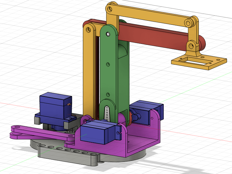
First thing was to design the hand. This design is based on design from this channel. It is designed around M4 screws. SG90 (alternatively MG9S) servos. Also the two arms (green and red on the image below) are same length, this will be usefull later to calculate inverse kinematics. Here is how the final designed looked like:
Download: robotic_arm.f3z
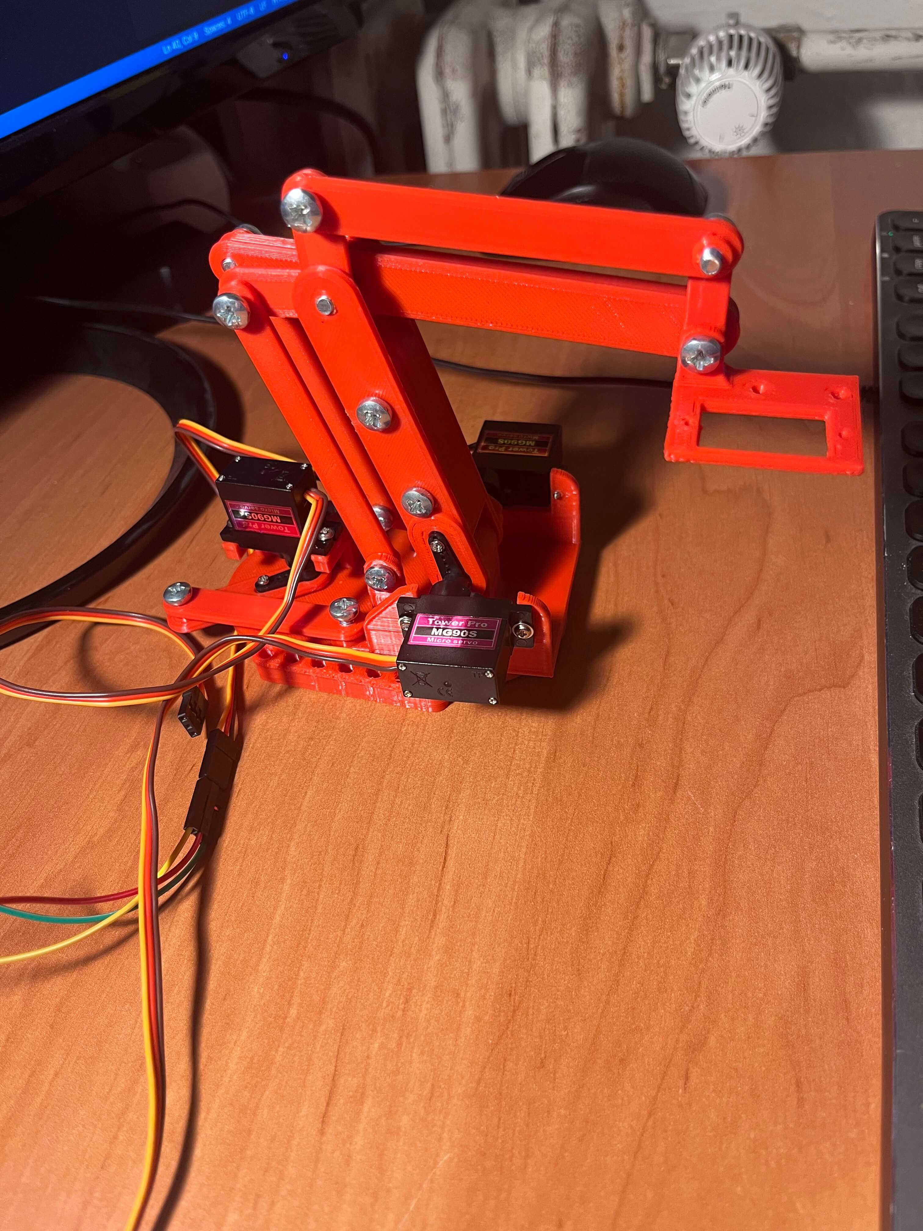
After assembling it, the robotic hand should look like this:
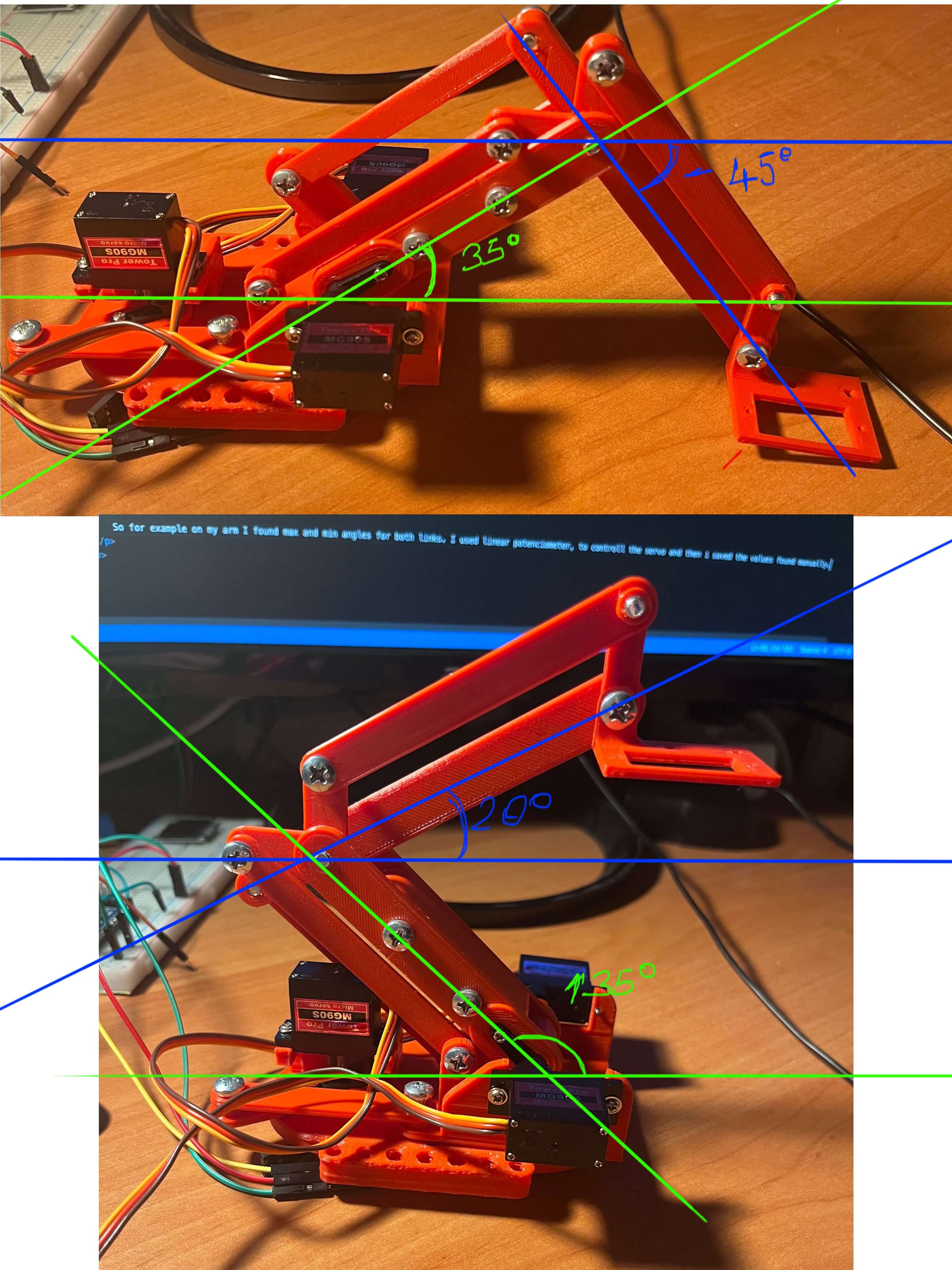
Now it is important to find, which angle on servo-motor corresponds to which angle on the arm-link (relative to the ground). It does not need to be super precise. If we wanted more precise controll, we would need better servos and ball bearings as pivots. We can't reach very high precision with this build.
So for example on my arm I found max and min angles for both links. I used linear potentiometer, to controll the servo and then i saved the values found manually. Here i found that for arm1 (green lines) 35 degrees relative to ground corresponds to 80 degrees on servo. 135 degrees corresponds to 0. For the arm2 (blue lines), -45 degrees is 70 on servo and 25 is 170 on servo.
Time for the fun stuff. Inverse kinematics.
First we start by "placing" our robot (or the pivot of the base arm) in the (0, 0, 0) origin. Now we start with a point in 3D space. Angle of the whole robot arm rotation can be calculated very easily as shown on the image below.
Alpha = atan(y/x).
now if we connect origin, our 3D point and its projection to x,y plane, we get right triangle and we can calculate its sides as show on the image.

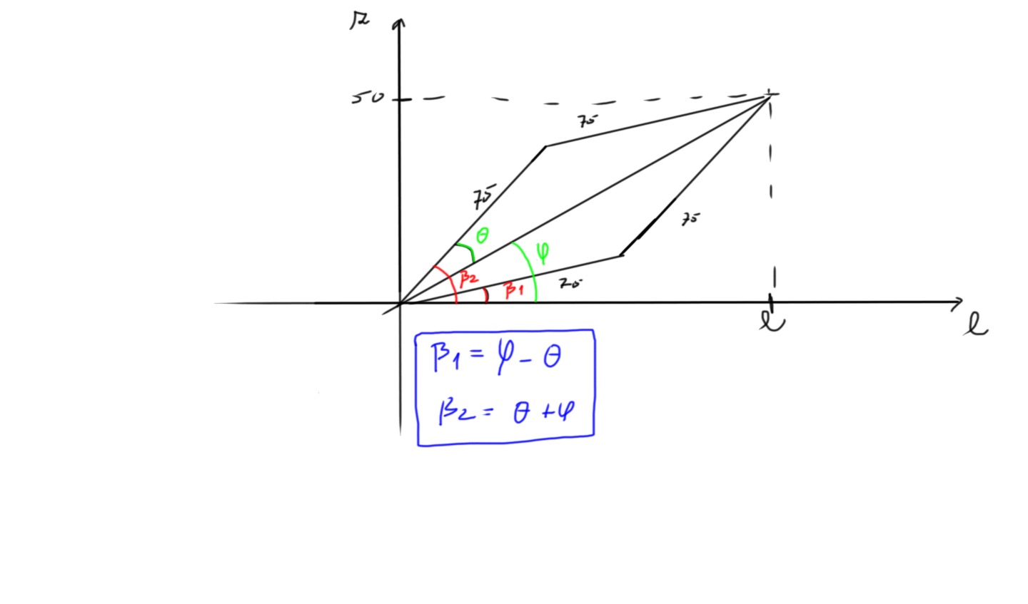
Now we switch to the plane of the created triangle. We can calculate angle phi and theta as shown on the image. Here we see, that the fact that the two arms are same lenght is simplifying our calculations.
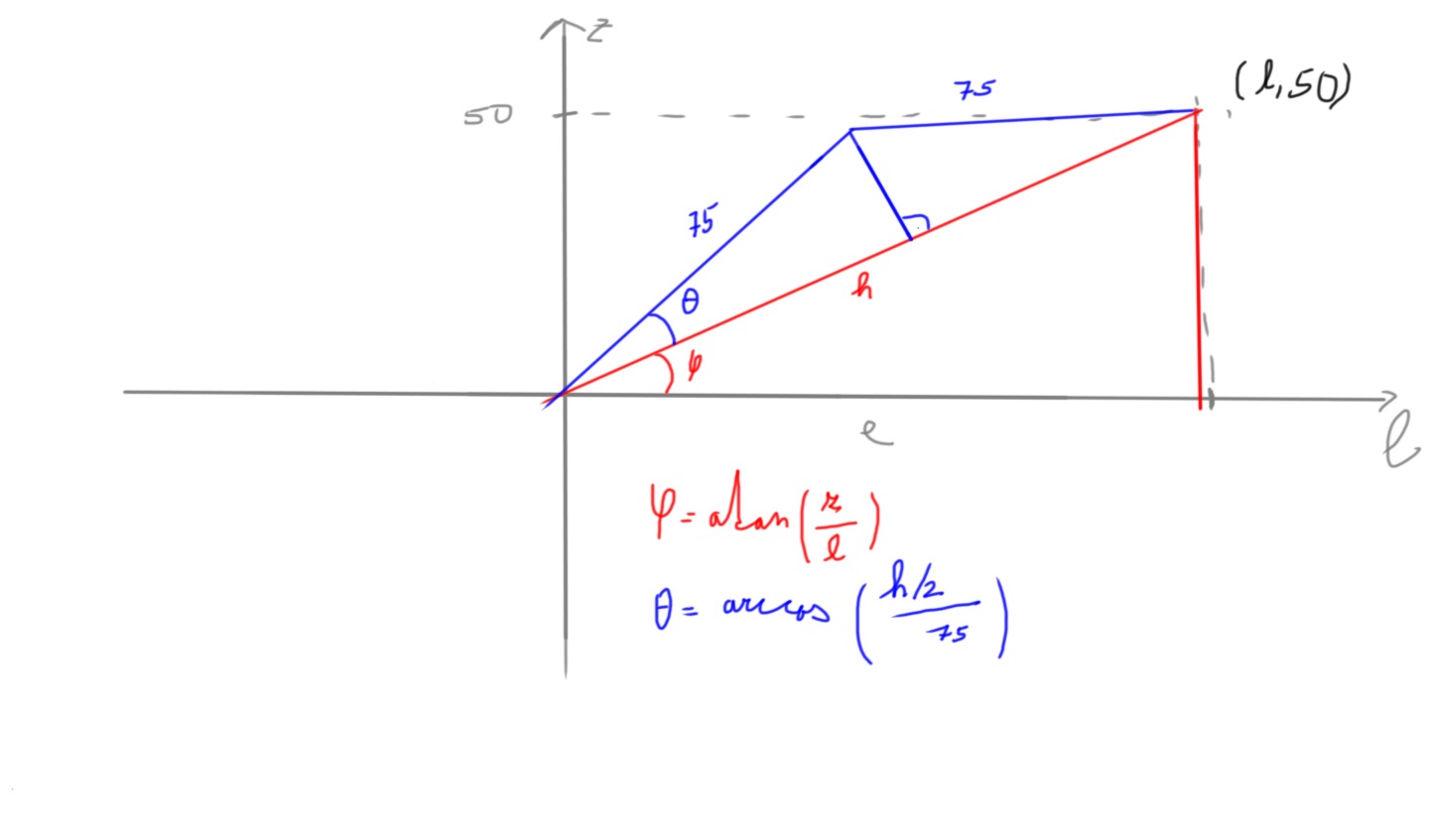
Now we can construct this parallelogram, where we know all the angles. Beta1 and Beta2 are our angles we are looking for. Beta1 is angle of the arm with blue lines drawn in the image shown before. Beta 2 is the angle of the arm with green lines.
Now we have all we need, to start writing code. This is now just metter of personal taste. I decided to create app in python, that can be controlled on pc, the angle data is then send to arduino, which sets the angles.
To the python app i added checking for unreachable positions and i have drawn out all reachable positons.
Python code is a bit longer and a bit complicated and not self explanatory (can be found on my gitLab). So i will just show the inverse kinematics calculation here:
def calc_ik(point):
    # point - [x, y, z]
    # arm1 - base arm
    # arm2 - end gripper arm
    l = math.sqrt(point[0] ** 2 + point[1] ** 2)
    fi = math.atan2(point[2], l)
    h = math.sqrt(point[2]**2 + l**2)
    theta = math.acos((h * 0.5) / (_REAL_ARM_LEN))
    angle_base = math.degrees(theta + fi)
    angle_gripper = math.degrees(fi - theta)
    return angle_base, angle_gripper
Here is the Arduino code, that accepts the data from serial port. Important is the "map" functions which converts the real-angles to servo angles.
#include

#define MAX_MSG_LEN 50

Servo arm_base;
Servo arm_gripper;
int servo_angle;
int prev_servo_angle = 0;
char inc_char;
char start_char = '<';
char end_char = '>';
char msg_buffer[MAX_MSG_LEN];

bool reading_msg = false;
bool msg_flag = true;
uint8_t rcv_num = 0;
int num_index = 0;
char received_nums[2][5];

void setup() {
    arm_base.attach(4);
    arm_gripper.attach(3);
    Serial.begin(115200);
    arm_base.write(33);
    arm_gripper.write(170);
}

void loop() {
    if(Serial.available() > 0){
    inc_char = Serial.read();
    if(!reading_msg && inc_char == start_char){
        reading_msg = true;
    }
    if(reading_msg && inc_char != start_char){
        if(inc_char == end_char){
        received_nums[rcv_num][num_index] = '\0';
        reading_msg = false;
        msg_flag = true;
        num_index = 0;
        rcv_num = 0;
        }
        else if(inc_char == '|'){
        received_nums[rcv_num][num_index] = '\0';
        rcv_num = 1;
        num_index = 0;
        }
        else{
        received_nums[rcv_num][num_index] = inc_char;
        num_index++;
        }
    }
    }
    if(msg_flag){
    // first num = angle for base, second num = angle for grip arm

    int angle_base = map(atoi(received_nums[0]), 130, 35, 0, 80);
    int angle_grip = map(atoi(received_nums[1]), 20, -45, 170, 70);
    arm_base.write(angle_base);
    arm_gripper.write(angle_grip);
    msg_flag = false;
    }
}
Finally here is the hand working: